What is metal 3D printing, and how does this additive process work? This article explains the core principles behind Selective Laser Melting (SLM) and Direct Metal Laser Sintering (DMLS), and explores how these technologies link to the main advantages and limitations of metal 3D printing
Selective Laser Melting (SLM) and Direct Metal Laser Sintering (DMLS) are both metal additive manufacturing processes within the powder bed fusion family of 3D printing. These technologies share many similarities: each uses a high-powered laser to scan and selectively fuse or melt metal powder particles, bonding them together to build a part layer by layer. In both cases, the raw material is a fine metal powder in granular form.
The key differences lie in the way particles bond (and also in their patent origins). SLM works with metal powders that have a single melting temperature and completely melts the particles, while DMLS uses powders made from materials with varying melting points that fuse at a molecular level under elevated heat.
In essence, SLM produces parts from a single metal, whereas DMLS is typically used to create parts from metal alloys.
The basic fabrication process is largely the same for both SLM and DMLS. It typically follows these steps:
The chamber is filled with an inert gas (such as argon) to reduce metal powder oxidation and is then heated to the optimal build temperature.
A thin layer of metal powder is spread over the build platform. A high-power laser then scans the cross-section of the part, melting or fusing the metal particles together to form a solid layer. This scanning covers the entire cross-section so that each layer is fully solid.
After each layer is complete, the build platform lowers by one layer thickness, and a recoater spreads a fresh layer of powder. This process repeats until the entire part is built.
Unlike polymer powder bed fusion processes such as SLS, large hollow sections are uncommon in metal 3D printing because support structures inside these cavities are difficult to remove. For internal channels larger than Ø8 mm, diamond or tear-drop cross-sections are recommended over circular ones, as they eliminate the need for internal supports. Additional design guidelines for SLM and DMLS are available in this article.
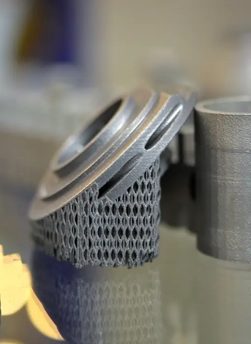
As an alternative to hollow sections, parts can be designed with skin and cores. These are processed with different laser powers and scan speeds, resulting in varying material properties. This approach is especially useful when producing parts with large solid sections, as it reduces print time and the risk of warping while maintaining high stability and excellent surface quality. Another common strategy in metal 3D printing to reduce weight is the use of lattice structures. Topology-optimization algorithms can also assist in designing organic, lightweight geometries.
A variety of post-processing techniques are used to enhance the mechanical properties, accuracy, and appearance of metal-printed parts. Essential steps include removing loose powder and support structures, while heat treatment (thermal annealing) is often employed to relieve residual stresses and improve mechanical performance.
For features requiring high dimensional accuracy—such as holes or threads—CNC machining can be applied. Additional finishing methods like media blasting, metal plating, polishing, and micro-machining can further improve surface quality and increase the fatigue strength of metal-printed components.